Esp8266: Difference between revisions
en>Illiteratebeef (Added pinout, links to software.) |
en>Illiteratebeef m (update info, better wording) |
||
| Line 1: | Line 1: | ||
The ESP8266 is a wifi SOC that has | The ESP8266 is a wifi SOC that costs $2-$10, has anywhere from 2 to 12 GPIO pins, can communicate using a wide variety of protocols, create and connect to 802.11 b/g/n networks, a simple web or telnet server, can be used in conjunction with an arduino, can store multiple programs in memory at once, and much more. | ||
It's | We have an ESP-01 board donated by Jason Nevins, that's stored by the arduino stuff. It's been preloaded with NodeMCU firmware and programmed to create a secured wifi access point, serve a webpage, and change a status LED on the device based on the status of a button on the page. Below is all the information you need to connect to the device and reprogram it any way you want. Please set it back to this state when you're done with it using [https://github.com/illiteratebeef/ESP8266Heatsync/blame/master/README.md this code]. | ||
The esp8266 can communicate with your computer using a USB to serial adapter and connecting it up to 3.3v power. The CH_PD pin needs to be brought high for the chip to run, a jumper has been soldered on the donated board so that you don't have to do this yourself. When you reprogram the firmware, the chip needs GPIO0 to be brought low. There is a pc jumper soldered to the board, so just bridge those pins if you need to burn new firmware. Otherwise, DO NOT bridge these pins as it will cause the chip to not boot. | It's highly recommended you watch [https://www.youtube.com/playlist?list=PLjzGSu1yGFjXMfptFXcXF2hi_ycBD2Lde these youtube videos], Especially part 3 and 4, and read the readmes for all of the NodeMCU and ESPlorer software. | ||
The esp8266 can communicate with your computer using a USB to serial adapter and connecting it up to 3.3v power. The CH_PD pin needs to be brought high for the chip to run, a jumper wire has been soldered on the donated board so that you don't have to do this yourself. When you reprogram the firmware, the chip needs GPIO0 to be brought low. There is a pc jumper soldered to the board, so just bridge those pins if you need to burn new firmware. Otherwise, DO NOT bridge these pins as it will cause the chip to not boot. | |||
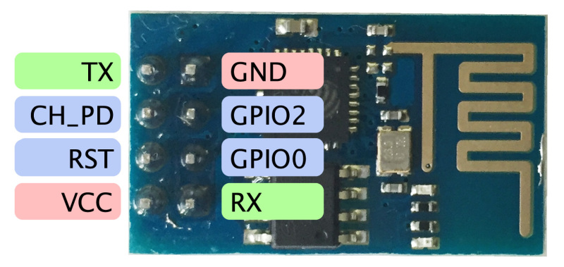
[[File:esp8266-pinout.jpg]] | [[File:esp8266-pinout.jpg]] | ||
| Line 12: | Line 13: | ||
SSID: ESP8266 -see wiki- | SSID: ESP8266 -see wiki- | ||
Password: 12345678 | Password: 12345678 | ||
Default IP of ESP board: 192.168.4.1 | |||
To burn the nodemcu firmware on the device, https://github.com/nodemcu/nodemcu-flasher | To burn the nodemcu firmware on the device, https://github.com/nodemcu/nodemcu-flasher | ||
Revision as of 04:49, 8 March 2015
The ESP8266 is a wifi SOC that costs $2-$10, has anywhere from 2 to 12 GPIO pins, can communicate using a wide variety of protocols, create and connect to 802.11 b/g/n networks, a simple web or telnet server, can be used in conjunction with an arduino, can store multiple programs in memory at once, and much more.
We have an ESP-01 board donated by Jason Nevins, that's stored by the arduino stuff. It's been preloaded with NodeMCU firmware and programmed to create a secured wifi access point, serve a webpage, and change a status LED on the device based on the status of a button on the page. Below is all the information you need to connect to the device and reprogram it any way you want. Please set it back to this state when you're done with it using this code.
It's highly recommended you watch these youtube videos, Especially part 3 and 4, and read the readmes for all of the NodeMCU and ESPlorer software.
The esp8266 can communicate with your computer using a USB to serial adapter and connecting it up to 3.3v power. The CH_PD pin needs to be brought high for the chip to run, a jumper wire has been soldered on the donated board so that you don't have to do this yourself. When you reprogram the firmware, the chip needs GPIO0 to be brought low. There is a pc jumper soldered to the board, so just bridge those pins if you need to burn new firmware. Otherwise, DO NOT bridge these pins as it will cause the chip to not boot.
ESP8266 Access Point Credentials:
SSID: ESP8266 -see wiki-
Password: 12345678
Default IP of ESP board: 192.168.4.1
To burn the nodemcu firmware on the device, https://github.com/nodemcu/nodemcu-flasher For example programs and pinout mappings: https://github.com/nodemcu/nodemcu-firmware For documentation on the nodemcu api: https://github.com/nodemcu/nodemcu-firmware/wiki/nodemcu_api_en To program the board over a serial connection, use this program: http://esp8266.ru/esplorer/
