Fakerbot: Difference between revisions
| Line 60: | Line 60: | ||
==Generate GCode== | ==Generate GCode== | ||
Open your stl file if you haven't already. Take a look at it in the preview window. | Choose File Open and open your stl file if you haven't already. Take a look at it in the preview window. [Picture of preview window] The preview window is the same size and shape as your available print area. The object shouldn't be hovering off the ground or spilling outside of the box. Click the "generate g code" button on the lower right. [Generate G Code button] This generates your 'tool paths', slicing the model into slivers and deciding how to print it. Next select the coreybot-noraft-test profile and click 'Generate'. [Picture of Skeinforge Selection] This may take some time. When this finishes you'll see a new tab next to model. [Picture of gcode tab] | ||
Next press the 'Upload to SD card' button. This will take a few minutes and forward all code over to the SD card so the machine can run | Next press the 'Upload to SD card' button. [Upload to SD card button] This will take a few minutes and forward all code over to the SD card so the machine can run all by itself, removing any delays the computer might cause. This is amazingly important as the little lenovo decides to take a break sometimes, ruining prints. | ||
==Warm up== | ==Warm up== | ||
Revision as of 12:50, 28 July 2011
The Makerbot is currently [working without a heated bed]
About
The machine is called a FakerBot, because it's not quite a MakerBot, but there is a direct lineage. Since we didn't have access to a laser-cutter and we wanted to do it on the cheap, the frame was slightly redesigned by Corey so that it could be cut on a tablesaw from inch material. The tongue and groove construction was replaced with dado-cut slots. All holes were made with a 7/8" forstner bit, this allows them to take a skate bearing (a paper shim is required) or anything else that we wanted through the use of adapter plates since we knew that mods were likely. Total cost of the enclosure was $13 for a sheet of 1/4" (actually 5.2mm) Luan from Home Despot which provided enough material to make four FakerBots even though we only made one. A laser-cut frame would have cost about $200 form Makerbot, so we saved a lot here. The frame was finished with linseed oil and came out pretty nice. MakerBot specified precision shafting for the X&Y axis which is unnecessary for a low-tech motion control system like this one. Drill rod was substituted for all linear shafting at a total cost of about $3 which is another $20 or $30 reduction. Similarly, low-cost nylon bushings were substituted for the more expensive MakerBot spec'd parts.
The X and Y stages on the MakerBot are pretty good aside from being too tall, however the Z-stage is a horrible design. It is overly complex, wobbly, prone to jamming, etc. A replacement z-stage was designed by Corey with the goal of making Z simple and reliable:
The following parts from the Makerbot design were removed:
- (1) Belt
- (8) Bearings
- (1) Driving Pulley
- (4) Driven Pulleys
- (2) Idler Pulleys
- (1) Platform
- (2) Extruder Mounts (Dragons)
- (4) All-thread Rods (leadscrews)
- (4) Driven nuts (leadnuts)
- assorted screws and hardware
That giant steaming pile of hardware was replaced with:
- (1) 1/4-20 Acme leadscrew
- (1) Antibacklash nut
- (1) shaft coupler
- (1) Cantilever arm (laser cut)
- (1) Linear rail
- (1) Truck for linear rail
An overall reduction from (27) functional components down to (6) !
If you count every nut and screw the reduction is far greater, but you get the idea. The new Z-stage is a big improvement and has eleminated all of the jamming and wobbling problems that we had previously. It also looks far better.
The extruder is Corey's design hosted at http://www.thingiverse.com/thing:4579. It is a clean-sheet of paper design that sprang from the frustration of dealing with the shortcomings of other extruders. So far the CoreyStruder and its derivatives have been downloaded on Thingiverse over 250 times.
The hot-end is Corey's copy of the hot-end used on the UP! printer which he later discovered is actually a copy of Nophead's design. It is very compact and works well. Nophead does awesome work, his blog is a must-read:
http://hydraraptor.blogspot.com/
Usage
Get a file
The best source online for files is probably Thingiverse If you're feeling up to it you can design your own file!! You need some sort of cad program. Some free possibilities include:
- Google Sketchup
- Blender
- OpenScad - This is neat because its not googlehical, its a 3d compiler! Its a programming language.
Whatever you use you need to export or save to STL format
Turn on
Make sure fakerbot is turned on (switch on power supply in back). The usb cable should be plugged in to your computer and the power supply should of course be plugged in.
Boot the machine on the desk and open ReplicatorG which should automatically connect to the board. Otherwise there is a connect button. [picture of connect button]
When properly connected the Status Bar will turn green. [Picture of green bar]
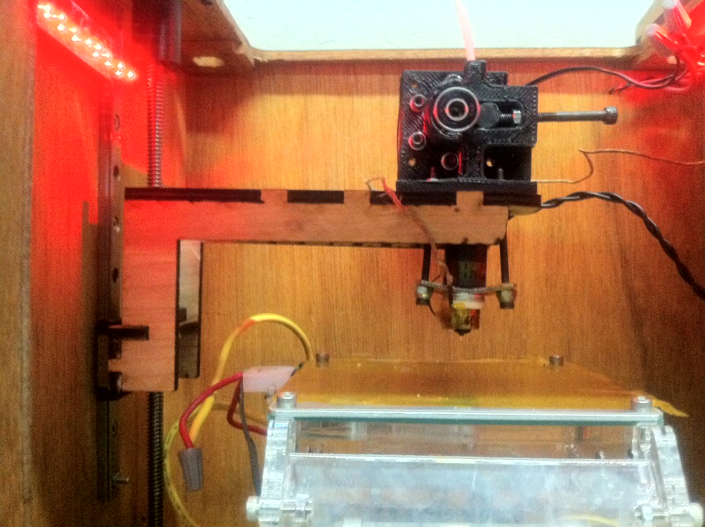
Get familiar with machine
The little table on the inside of the machine will be referred to as the build platform, or heated build platform. [Picture of platform] This platform is often heated to aid in printing. The little nozzle above the table will be referred to as the extruder. [Picture of extruder] The extruder is also heated in order to melt the plastic and push it through the nozzle 'extruding' it.
Generate GCode
Choose File Open and open your stl file if you haven't already. Take a look at it in the preview window. [Picture of preview window] The preview window is the same size and shape as your available print area. The object shouldn't be hovering off the ground or spilling outside of the box. Click the "generate g code" button on the lower right. [Generate G Code button] This generates your 'tool paths', slicing the model into slivers and deciding how to print it. Next select the coreybot-noraft-test profile and click 'Generate'. [Picture of Skeinforge Selection] This may take some time. When this finishes you'll see a new tab next to model. [Picture of gcode tab]
Next press the 'Upload to SD card' button. [Upload to SD card button] This will take a few minutes and forward all code over to the SD card so the machine can run all by itself, removing any delays the computer might cause. This is amazingly important as the little lenovo decides to take a break sometimes, ruining prints.
Warm up
We need to heat up the tip for ~5 minutes and extrude some plastic in order to get the machine operational.
Click the Control panel button (arrows) and set Motor Speed PWM to 255, target temp to 230. You must press enter or click your cursor outside of that input box in order to make this take effect. You're probably using a heated bed as well so set that temperature to 100 and wait for it to reach at least 90 to 95C. Note: You'll need to wait quite a while for this to reach its final temperature. Make sure that it is a consistent temperature across the entire surface to prevent corners form peeling.
The machine should immediately begin moving towards temp (theres a temperature graph below, with red as your temperature) and reach it within a minute or two tops.
While this happens get comfortable with the X, Y and Z controls. They move for the distance set in the Jog Size column. Be careful not to jam the head into the table or the sides!
Using the controls make it so the extruder at least 10 or 20mm off the table. No need to be perfect(you can eyeball this). Go ahead and click forward on the motor control which is under the pinch wheel extruder tab. Watch the bearing and the gear on the extruder. Both should be turning. If not stop the motor and wait for the barrel to heat up more and or help the extruder along by twisting the filament.
By now you should be freely flowing plastic or you've got a blocked heater barrel or your pinch wheel setup is not adjusted properly. You should find help or start googling (try the makerbot and or fakerbot sites).
Run the plastic for at least a few minutes, making sure the plastic doesn't pile up and touch the tip.
Zero machine
Fakerbot doesn't know or care where it starts, you must pick your 'zero' before you print. For us thats the direct center of the platform with the nozzle touching the platform.
Still in the control panel, set your 'jog' size (larger sizes are larger moves, BE CAREFUL YOU DON'T CRASH THE HEAD!). Click the arrows x+,x-,y+,y-,z+,z- to move the platform around so the nozzle is right in the center. Put a piece of paper down on the platform and slowly move the toolhead down using increasingly smaller jog sizes. You want to have the toolhead touch the paper and have a bit a drag, but still be able to remove the paper.
When you think you have it, and your toolhead is in the middle of your x and y axis as well, press 'Set Zero'.
Print!
Clear any the nozzle, click to zero the z, and click 'Build' from the main makerbot menu.
The build may take a bit to start while it achieves optimal temperatures. Note where the stop button is on the control panel in case anything looks bad. Presumably the print will start, adhere to the bed well, and you can simply stick around until your print finishes.
Status Updates
3/29/2011
We will hope to keep updates here. Most recently Jacob adjusted the z and one of the x/y reference voltages down to keep the motors coolor. So far everything seems fine. Will want to adjust the other X/Y voltage down as well if everything remains awesome. I've also restricted the build envelope a bit more to hopefully match the machine. Finally we had an issue with Z stage binding during prints. I found the feedrate was set to 1000 in the machines.xml file, and I've moved this down to 100. I'm sure we can bump this a bit eventually but for now its good.
3/30/2011
We are slimming down the Build Platform to give us another 3/4" of vertical build room. [1] Also modifying the the Z-Stage arm to give another 2"-2.5" of vertical build room.
4/7/2011
After adding the Z-axis modification, Mods of z-axis there are some programming things that need to be cleaned up. Some objects print well, some print great, and others, are complete crap. Flickr page
4/20/2011
- pid was very noisy, followed http://wiki.makerbot.com/thingomatic-doc:calibration and set it to standard mk5 settings P : 6.25 I : 0.4140625 D : 100.0 (which we should be very close to) and it looks great now
- took off probably 4/5 of the heatsink compound. There appeared to be too much and it was actually drying out. Theres a small sheen on both sides now (which i fear is still probabyl 2x too much) but I think will help
- Finally got the outline module on! just took the 35 version and enabled it for 39. This draws a box around the print first which lets the extruder catch up and plastic to stick to platform -before- it enters your object
- I've taken over 50mm away from the x axis as it was massively oversized and crashing the heated build platform connectors into the cantilever.
- Used Dave Durant's suggestions at http://davedurant.wordpress.com/2010/11/06/configuring-skeinforge-making-a-new-profile/ and without any real tweaking the 20mm test cubes look REALLY good
4/24/2011
- Did some work on the spindle filament holder. Had some notches in the circular base and top that were catching on the sides that I filed down.
- Bolts and nuts were too small connecting the circular bearing for the lazy susan to the chassis. Drilled out holes and replace with bigger bolts and nuts.
4/28/2011
- Corey designed a new Cantilever to gain more z height. He's staining it before installing.
- Jacob created a new heated build platform plate. We were using the automated build platform, but it reduces our z and we're not ready to implement it yet. The main hold up was the files online weren't fitting our platform. Corey's design files in some areas differ from Makerbot's as he had to reverse engineer them. I used Corey's files which fit fine. I also scaled down the bolt holes to fit our bolts to remove the x/y wobble. Sadly, theres still some wobble that must have to just do with their implementation. The wires from the heated platform were moved to the right as well, adding some x. The makerbot file was updated for the extra room.
7/04/2011
- Heated Build platform solder points eventually work hardened and broke the solder pads from the board. Next build platform iteration needs through hole connectors for stability. Thermistor also gave massive trouble during this point but has been replaced and appears to be printing well again.
7/16/2011
- Heated Build platform out again due to solder points.. Designed new one and sending out for printing.
Todo
- wobble in z axis???--need to buy new acme rod
- z 'bubble' is pretty bad. Need to speed up z axis...
- fix spindle box -- needs new 'posts' to hold filament and needs new acrylic window
- 'magnetic' cables on build platform would be awesome
- functional lighting (build platform is red when hot, blue when cold, yellow when heating
- stepper extruder (wade? something else)
- looooots of ooze -- reversal params? or might only be correctable with a stepper?
- limit switches installed
- pick up a digital indicator for leveling platform
- light ring around extruder to light platform
- hook up an estop
- second (or even third) entire extruder ready to go
- quick change extruder assembly