Fakerbot: Difference between revisions
en>Jjrosent |
en>Jjrosent (added putting replicator g on your laptop section) |
||
| Line 1: | Line 1: | ||
=The Makerbot is currently [ | =The Makerbot is currently [awesome] = | ||
=Usage= | =Usage= | ||
| Line 30: | Line 30: | ||
The build may take a bit to start while it achieves optimal temperatures. Presumably the print will start, adhere to the bed well, and you can simply stick around until your print finishes. If it messes up stay calm, press the stop button or in the worst case turn the machine off and either try again or ask for help. | The build may take a bit to start while it achieves optimal temperatures. Presumably the print will start, adhere to the bed well, and you can simply stick around until your print finishes. If it messes up stay calm, press the stop button or in the worst case turn the machine off and either try again or ask for help. | ||
=Putting Replicator G on your laptop= | |||
You can indeed install replicatorg on your laptop for most likely superior performance to the lenovo. You may also be able to get away with not using an SD card. Go to replicat.org and download ReplicatorG 26 or higher. You'll need to change 2 files, [[file:fakerbot.xml]] and [[file:start.txt]]. fakerbot.xml goes into the machines directorty. start.txt is a little more tough. It goes under skein_engines/skeinforge-0006/prefs/thingomatic-mk5-heated-abs AND skein_engines/skeinforge-0006/prefs/thingomatic-mk5-abs. Those will also be the profiles you will want to print from. One last, annoying change. When you go to generate your g code with those profiles, you need to go into each and go into the carve menu and change your layer height depending on the filament size. We're at .4 right now instead of the default .36. | |||
==Post Processing of Printed Items== | ==Post Processing of Printed Items== | ||
Revision as of 01:31, 28 October 2011
The Makerbot is currently [awesome]
Usage
Get a file
The best source online for files is probably Thingiverse If you're feeling up to it you can design your own file!! You need some sort of cad program. Some free possibilities include:
- Google Sketchup
- Blender
- OpenScad - This is neat because its not googlehical, its a 3d compiler! Its a programming language.
Whatever you use you need to export or save to STL format
Turn on
Make sure fakerbot is turned on (switch on power supply in back). The usb cable should be plugged in to your computer and the power supply should of course be plugged in.
Boot the computer on the desk and open ReplicatorG which should automatically connect to the board. Otherwise there is a connect button. [picture of connect button]
When properly connected the Status Bar will turn green. [Picture of green bar]
Get familiar with machine
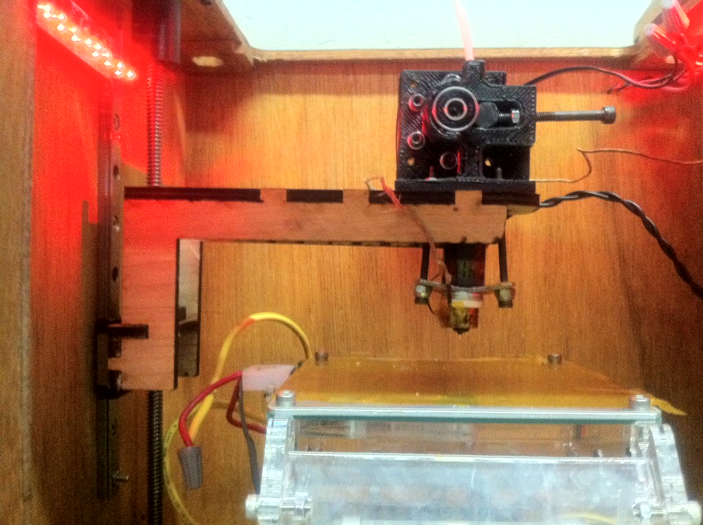
The little table on the inside of the machine will be referred to as the build platform, or heated build platform. [Picture of platform] This platform is often heated to aid in printing. The little nozzle above the table will be referred to as the extruder. [Picture of extruder] The extruder is also heated in order to melt the plastic and push it through the nozzle 'extruding' it. Click the arrow keys icon [Picture of Control Panel Icon] Here you can manually heat up machine or move the head around. Note that the X and Y movement directions are probably reversed from what you might think. X- moves to the right and X+ moves to the left! Y- moves backwards and Y+ moves towards you! Z+, however moves up as you'd expect, and Z- down. Close this window.
Generate GCode
Choose File->Open and open your stl file if you haven't already. Take a look at it in the preview window. [Picture of preview window] The preview window is the same size and shape as your available print area. The object shouldn't be hovering off the ground or spilling outside of the box at all! If all looks good click the "generate g code" button on the lower right. [Generate G Code button] This prepares the file for printing by slicing the model into slivers and deciding how best to print it. Next select the thingomatic-mk5-heated profile and click 'Generate'. [Picture of Skeinforge Selection] This may take some time. When this finishes you'll see a new tab next to model. [Picture of gcode tab]
Send to SD card
Next press the 'Upload to SD card' button. [Upload to SD card button] This will take a few minutes and forward all code over to the SD card so the machine can run all by itself, removing any delays the computer might cause. This is amazingly important as the little lenovo decides to take a break sometimes, ruining prints.
Print!
You're ready! Note where the stop button is on the control panel in case anything looks bad. Also note the power switch in back of the machine. If something goes wrong, these are your friends. Now click 'Build from sd card' [build from sd card] from the main makerbot menu.
The build may take a bit to start while it achieves optimal temperatures. Presumably the print will start, adhere to the bed well, and you can simply stick around until your print finishes. If it messes up stay calm, press the stop button or in the worst case turn the machine off and either try again or ask for help.
Putting Replicator G on your laptop
You can indeed install replicatorg on your laptop for most likely superior performance to the lenovo. You may also be able to get away with not using an SD card. Go to replicat.org and download ReplicatorG 26 or higher. You'll need to change 2 files, File:Fakerbot.xml and File:Start.txt. fakerbot.xml goes into the machines directorty. start.txt is a little more tough. It goes under skein_engines/skeinforge-0006/prefs/thingomatic-mk5-heated-abs AND skein_engines/skeinforge-0006/prefs/thingomatic-mk5-abs. Those will also be the profiles you will want to print from. One last, annoying change. When you go to generate your g code with those profiles, you need to go into each and go into the carve menu and change your layer height depending on the filament size. We're at .4 right now instead of the default .36.
Post Processing of Printed Items
The following is taken from http://www.thingiverse.com/thing:12759 posted under CC BY SA license and reproduced here. See that link for the most up to date document. Authors: Mark Gaffney Version: 1.3D Date: 2011-10-14
Once your parts are printed you may want or need to perform some additional steps to turn them into a fully finished item. These steps are generally referred to as Post-Processing. Post-Processing tend to involve the following sequential steps:
- Removing Parts – Taking the object from the printer and separating individual parts or structures
- Cleaning-up Parts – Removing rafts, support structures and “strings”
- Refining Features – Resizing holes, rounding edges and sharpening details
- Assembly – Combining printed and non-printed parts
- Finishing –Mechanically filing, sanding and polishing as well as chemically or heat treating objects to improve the surface finish
Removing your print
When the printer stops extruding, the build platform will move so that the nozzle is positioned at the back of the build platform. However the print is not yet completed, the printer enters a cool down period to allow the hot surfaces and printed object to cool down slightly. Until this cool down time has elapsed the operator should not reach into the printer to remove the printed object. The printer has cooled down sufficiently when the build platform moves forward slightly further and the build platform motor is engaged. If you were using the direct print method, a dialog box message will also appear in ReplicatorG. If you have a conveyor belt installed on the platform the parts should be ejected automatically, if not you will have to reach inside to remove the printed part. If you need to remove the part by hand like so it may be worth waiting until the build platform cools down further before removing the printed part. The main reason for this is that the inside surfaces of the printer are still very hot, presenting an injury risk to the operator, however as the mass of extruded thermo-plastic may still be quite hot it might not be solid enough to remove without damaging or warping the printed part. Also, for many material combinations (such as ABS on Kapton and Aluminium) the mismatch between the coefficient of thermal expansion of the printed part and the build platform will often cause the part to detach itself from the build platform as it cools. If this does not happen, a small amount of additional pressure applied with your fingers, a tweezers or a paint scraper should easily remove the printed part from the build platform. Avoid the temptation to use a sharp knife as the tip is liable to break off or slip, potentially injuring the operator, damaging the build surface and leaving a sharp piece of metal embedded in your printed object. Further post-processing can now be attempted. Separating Parts Often when printing large numbers of parts, it is more economical and efficient to print multiple parts at a time on the one printer. For this reason many people have prepared such multi part printing plates. These plates are often very densely packed with parts so that separating them is not a straight forward task. With increased use of multi-material prints with soluble support structures this will hopefully become less of an issue, with the as-printed group simply being left in a bath of a suitable solvent to allow the parts to separate themselves. Separating items from the same raft can generally be easily performed using a knife or scissors to cut along the gaps between individual parts, in some cases where the gap between adjacent parts is sufficiently large and straight this may also be done by repeatedly flexing the conjoined parts back and forth until the raft snaps. Additional support structures may need to be removed to totally separate parts Separating items from the same piece of support structure (whether user created or automatically generated) is often not straight forward and may require several methods. If the support structure is very thin and shallow it may be cut with a scissors etc. or (if the parts are also reasonably strong) flexed back and forth until it snaps. If it is very large and dense it may need to be cut through using a heavy knife, saw, dremel cutting tool or a combination of these. If some internal support structures are not easily accessible repeatedly gently flexing the joined objects back and forth can break the connections between them. An operator should bear in mind the need for individual objects can be easily separated from each other when designing a multi-part print.
Removing Rafts
Rafts can help the bottom layers to stick to the build platform and prevent curling, it can also allow and operator to produce good quality prints on a poor quality, non-level or uneven build surface. A Raft is a thin (often only 2 or 3 layers thick), sacrificial, waffle-like structure built beneath the object to be printed at the start of each print. Rafts tend to extend beyond the maximum size of the printed object by several millimetres so that any curling or lifting of the raft will be less likely to affect the printed object above it. The first layer of the raft is often printed much slower, wider and deeper than normal layers to help it adhere to and to fill-in the potentially uneven surface of the build platform. The final layer of the raft is often printed much quicker, thinner and shallower than normal layers to provide a reasonably weak bond to the printed object above it for easier removal after printing. If the printer is setup correctly, the raft should easily peel away from the base of the object by hand. If the object is very delicate, or parts of the raft become stuck, a blunt plastic or metal tool such as a spudger or scraper may be helpful to gently pry the two sections apart. If this doesn’t work, repeatedly scoring along the join between the raft and object with a sharp knife should help. If an operator decides to use a knife they should wear protective gloves and eyewear and know the location of the nearest first aider. The operator should be careful to cut away from their hand and in the event they cut themselves (once first aid has been administered) dispose of the responsible sharp object in the yellow medical waste sharps bin for correct disposal.
Removing strings
Fine lines of plastic often connect the elements of your print where they should not. These strings are generally formed where the hot end moves between 2 unconnected parts on the same layer. Although the extruder motor should be stopped as it moves between these 2 locations, a small amount of plastic may continue to exit or is drawn out of the hot end during this motion. The plastic forms a very narrow filament connecting the 2 locations. As the locations where it stops printing one unconnected feature and starts printing the other may vary widely between layers, this can lead to a large number of strings connecting seemingly random points on each feature. The size and number of strings can be reduced by moving from a DC motor to a stepper motor, enabling reversal in skeinforge and fine tuning reversal settings, but even so it may be difficult to eliminate entirely. If stringing is an issue for your printer it is possible to design-in additional narrow structures between separate features to prevent stringing. If the strings are all located on top of one another they will form a narrow membrane, which, if you have free access to them, can be easily removed by scoring along the join between the membrane and the object with a sharp knife. Large numbers of short, thin and randomly located strings can be easily removed by rubbing a blunt edged object repeatedly back and forth across the surface where they are located, they will tend to snap off from the object where they connect. Some strings, especially if they are longer and thicker may be easier to remove by cutting across their base with a sharp edge, it may help to pull on the end of the strings to apply tension to them. Operators should any such sharp tools in a responsible manner and only during business hours when a known first aider is available. As mentioned above removing support structures can be complicated. Generally the parts should only loosely connected to the support structure such that they can easily be broken off by hand, however if the supported part is very delicate or the support structure settings for that printer are not well calibrated this can cause damage to the object you have printed. If there are a flat surfaces and straight edges between the part and support a scalpel of knife can be used to score along the join between the two, weakening the connection between the two so that they fall apart or become weak enough that they can be easily separated by hand. If the support structure is very large, the part it protects very delicate, or complex in shape the supporting structure may need to be slowly removed in layers with a knife or scalpel and tweezers, working closer and closer to surface of the object. An operator should always attempt to design a part in a way that minimises the use of support structures as these can lead to significant waste of materials and time. By changing orientation, splitting parts into smaller entities that require less support, or creatively arranging multiple parts on a build platform so that they support each other it is possible to significantly reduce this waste.
Gauging & rounding circular holes
When making circular holes they will often not be printed as expected. For horizontal holes, they often become flattened near the top as the hot plastic droops, this gets worse as the diameter increases. For vertical holes they will often have flat spots or be somewhat elliptical due to low model resolution, backlash in the gears or low tension in the belts connected to the XY stage. Most printed holes, even if round, will not be the same size when printed as they are in the design due to the molten material that makes up their walls flowing or dropping into their void. Small holes, either vertical or horizontal, can completely close over for similar reasons. Also in some parts holes may contain strings or support structures. If the diameter, roundness and straightness is not critical the holes can be cleaned by hand using a suitably sized round file, drill bit or even a piece of printer filament. If the diameter, roundness and straightness of a hole is critical to your design they will need to be measured and carefully bored out to the correct size. A wide range of drill bits and files, a drill press and calipers make this reasonably easy. All such holes should be measured with a calipers in at least the 2 main dimensions (i.e. in X&Y for a vertical hole and X&Z or Y&Z for a horizontal hole). These measurements should be compared to the target size taken from the original designs. The part should be orientated, clamped and centered correctly for drilling in the drill press and starting with a drill bit smaller than the smallest distance/diameter and working up in steps to the target diameter slowly bored out to the desired diameter. Wood drill bits and medium to low speeds are ideally suited to drilling most types of plastic, repeatedly plunging and removing the drill as you slowly work to the required depth will help prevent the drilled plastic fragments from clogging the hole and melting to the drill bit. If the drill appears to be covered in melted plastic the user should remove it, clean it off and reduce their drill rotation speed or rate of progress. During this procedure the operator should take care that the drill hole remains centered in the correct location, using a calipers or similar item to measure to a known datum. The operator should make sure that they receive appropriate training for any tools they need to use and observe appropriate safety precautions, such as ensuring the operator and any nearby individuals wear safety goggles when drilling, filing etc.
Making edges round and surfaces smooth
The resolution of the 3d printer and the level of detail of the 3D model used will often leave round features looking stepped or faceted and flat surfaces with a ridged texture, poor alignment of axes and leadscrews can add to this further decreasing surface smoothness. Roundness can be regained using files, sandpaper and acetone. Starting with a coarse file and moving up to fine files, coarse sandpaper and medium sandpaper, the edges should be rounded off. To get a final glossy smoothness a thin coat of acetone can be brushed on or applied by dipping. Operators should ensure they follow all safety precautions including use of correct gloves and proper ventilation when dealing with acetone.
Squaring Rounded holes
The molten nature of the plastic will tend to round off many sharply detailed features, if these are critical to your design they will need to be adjusted by hand using hand files. Fine files with triangular and square cross section are available and very useful for sharpening the internal edges of many features.
Joining Pieces and filling holes
Acetone is a good solvent for ABS plastic. Using pure acetone applied with a paintbrush a reasonably smooth printed object can be given a high quality glossy sheen. By placing a part with poor surface finish in a bath of Acetone it will help smooth out all the lumps and bumps in the surface and give a smooth, organic looking surface, care should be taken when doing this that the part is not left in for too long or it will dissolve. By dissolving scrap ABS in acetone a more viscous product can be made with many uses, the viscosity and useful applications will depend on the ratio of ABS to Acetone. Low amounts of ABS create a product that can be applied with a brush that is useful for filling gaps in and giving a glossy surface to as-printed parts or for gluing very flat parts together. Medium amounts of ABS give a thicker, more glue-like material which is effective as a small-hole filler and glue for less even surfaced 3d printed items. Large amounts of ABS gives a thick paste that can be applied with a palette knife or spatula that can be used for effectively filling holes and attaching very differently shaped parts whose mating surface contours do not well match to each other or even for moulding and shaping additional parts by hand. Any work involving acetone should be performed in a well ventilated area, away from high temperature surfaces and sources of ignition. If the operator will come into contact with acetone or parts that have recently been in contact with acetone products suitable protective gloves (such as disposable powder-free blue nitrile or N-Dex) should be worn to prevent acetone from being absorbed into the operators body through the skin and reduce the chance of a user becoming stuck to or leaving fingerprints on “wet” printed items.
Status Updates
10/24/2011
New Makerbot(tm) heated bed installed to see if its any more reliable than my home built set up. Before we could really find out though the Motherboard is losing its firmware??? I reflashed it but now the SD card doesn't work, and I hear it won't respond again now so needs reflashing again. The only thing I can think of is power supply issues, and separately a need to reflow the SD card.
10/19/2011
Tried a new shipment of thermistors and another board and so far so good. Saw one oddity but it went away? Installed 3 new endstops on the machine and built homing code. This is allowing us to tap into the Thingomatic homing, and delete all the 'zero' calibration steps from above! Also upgraded to ReplicatorG 26 and new firmware (no going back!) and went back down to the default skeinforge (6?) ditching old profiles and staying stock for now.
10/01/2011
- New boards arrived, LOTS of trouble with thermistors dying now. Still haven't tracked it down. Another symptom is the extruder board losing its firmware and/or bootloader.....Still testing.
7/16/2011
- Heated Build platform out again due to solder points.. Designed new one and sending out for printing.
7/04/2011
- Heated Build platform solder points eventually work hardened and broke the solder pads from the board. Next build platform iteration needs through hole connectors for stability. Thermistor also gave massive trouble during this point but has been replaced and appears to be printing well again.
4/28/2011
- Corey designed a new Cantilever to gain more z height. He's staining it before installing.
- Jacob created a new heated build platform plate. We were using the automated build platform, but it reduces our z and we're not ready to implement it yet. The main hold up was the files online weren't fitting our platform. Corey's design files in some areas differ from Makerbot's as he had to reverse engineer them. I used Corey's files which fit fine. I also scaled down the bolt holes to fit our bolts to remove the x/y wobble. Sadly, theres still some wobble that must have to just do with their implementation. The wires from the heated platform were moved to the right as well, adding some x. The makerbot file was updated for the extra room.
4/24/2011
- Did some work on the spindle filament holder. Had some notches in the circular base and top that were catching on the sides that I filed down.
- Bolts and nuts were too small connecting the circular bearing for the lazy susan to the chassis. Drilled out holes and replace with bigger bolts and nuts.
4/20/2011
- pid was very noisy, followed http://wiki.makerbot.com/thingomatic-doc:calibration and set it to standard mk5 settings P : 6.25 I : 0.4140625 D : 100.0 (which we should be very close to) and it looks great now
- took off probably 4/5 of the heatsink compound. There appeared to be too much and it was actually drying out. Theres a small sheen on both sides now (which i fear is still probabyl 2x too much) but I think will help
- Finally got the outline module on! just took the 35 version and enabled it for 39. This draws a box around the print first which lets the extruder catch up and plastic to stick to platform -before- it enters your object
- I've taken over 50mm away from the x axis as it was massively oversized and crashing the heated build platform connectors into the cantilever.
- Used Dave Durant's suggestions at http://davedurant.wordpress.com/2010/11/06/configuring-skeinforge-making-a-new-profile/ and without any real tweaking the 20mm test cubes look REALLY good
4/7/2011
After adding the Z-axis modification, Mods of z-axis there are some programming things that need to be cleaned up. Some objects print well, some print great, and others, are complete crap. Flickr page
3/30/2011
We are slimming down the Build Platform to give us another 3/4" of vertical build room. [1] Also modifying the the Z-Stage arm to give another 2"-2.5" of vertical build room.
3/29/2011
We will hope to keep updates here. Most recently Jacob adjusted the z and one of the x/y reference voltages down to keep the motors coolor. So far everything seems fine. Will want to adjust the other X/Y voltage down as well if everything remains awesome. I've also restricted the build envelope a bit more to hopefully match the machine. Finally we had an issue with Z stage binding during prints. I found the feedrate was set to 1000 in the machines.xml file, and I've moved this down to 100. I'm sure we can bump this a bit eventually but for now its good.
Todo
- wobble in z axis???--need to install new acme rod
- z 'bubble' is pretty bad. Need to speed up z axis...
- fix spindle box -- needs new 'posts' to hold filament
- 'magnetic' cables on build platform would be awesome
- functional lighting (build platform is red when hot, blue when cold, yellow when heating
- looooots of ooze -- reversal params? or might only be correctable with a stepper?
- pick up a digital indicator for leveling platform?
- light ring around extruder to light platform
- hook up an estop
- quick change extruder assembly
- echangable parts to keep machine running - another extruder assembly, heated bed assembly, etc
About
The machine is called a FakerBot, because it's not quite a MakerBot, but there is a direct lineage. Since we didn't have access to a laser-cutter and we wanted to do it on the cheap, the frame was slightly redesigned by Corey so that it could be cut on a tablesaw from inch material. The tongue and groove construction was replaced with dado-cut slots. All holes were made with a 7/8" forstner bit, this allows them to take a skate bearing (a paper shim is required) or anything else that we wanted through the use of adapter plates since we knew that mods were likely. Total cost of the enclosure was $13 for a sheet of 1/4" (actually 5.2mm) Luan from Home Despot which provided enough material to make four FakerBots even though we only made one. A laser-cut frame would have cost about $200 form Makerbot, so we saved a lot here. The frame was finished with linseed oil and came out pretty nice. MakerBot specified precision shafting for the X&Y axis which is unnecessary for a low-tech motion control system like this one. Drill rod was substituted for all linear shafting at a total cost of about $3 which is another $20 or $30 reduction. Similarly, low-cost nylon bushings were substituted for the more expensive MakerBot spec'd parts.
The X and Y stages on the MakerBot are pretty good aside from being too tall, however the Z-stage is a horrible design. It is overly complex, wobbly, prone to jamming, etc. A replacement z-stage was designed by Corey with the goal of making Z simple and reliable:
The following parts from the Makerbot design were removed:
- (1) Belt
- (8) Bearings
- (1) Driving Pulley
- (4) Driven Pulleys
- (2) Idler Pulleys
- (1) Platform
- (2) Extruder Mounts (Dragons)
- (4) All-thread Rods (leadscrews)
- (4) Driven nuts (leadnuts)
- assorted screws and hardware
That giant steaming pile of hardware was replaced with:
- (1) 1/4-20 Acme leadscrew
- (1) Antibacklash nut
- (1) shaft coupler
- (1) Cantilever arm (laser cut)
- (1) Linear rail
- (1) Truck for linear rail
An overall reduction from (27) functional components down to (6) !
If you count every nut and screw the reduction is far greater, but you get the idea. The new Z-stage is a big improvement and has eleminated all of the jamming and wobbling problems that we had previously. It also looks far better.
The extruder is Corey's design hosted at http://www.thingiverse.com/thing:4579. It is a clean-sheet of paper design that sprang from the frustration of dealing with the shortcomings of other extruders. So far the CoreyStruder and its derivatives have been downloaded on Thingiverse over 250 times.
The hot-end is Corey's copy of the hot-end used on the UP! printer which he later discovered is actually a copy of Nophead's design. It is very compact and works well. Nophead does awesome work, his blog is a must-read: